Description
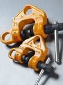
Screw Clamp Features
Screw Clamp Features
Features
? A circular double cam lock method is employed, resulting in a stronger clamping force and ensuring safe work.
The circular cams on both sides are supported by hemispherical surfaces, so they apply a clamping force to the suspended load while rotating according to the load direction.

- Two suspension holes enable work to be performed in all directions.
There are two suspension holes, one for vertical suspension and the other for horizontal suspension, enabling the load to be hoisted in either orientation.
- This is the lightest clamp in the industry.
The body, cam and screw are formed from special alloy steel, and have excellent strength and toughness due to our unique heat treatment technology, thus enabling the clamp to be successfully miniaturized.
- This clamp can be used to hoist inclined loads such as I-beams.
The gripping pieces enable the load to be hoisted while inclined at an angle of up to 10 degrees without slipping off.
- The setscrew of the screw is a fine thread type.
Because the setscrew produces a high clamping force and does not readily become loose, the clamp is highly resistant to vibration. In addition, the head of the screw is hexagonal (21mm between flats), enabling it to be turned using a ratchet wrench.
- The body is provided with a baked finish, and the circular cam and the screw are treated to prevent rusting.
Specifications

Specifications
|
Model
|
Capacity
( t )
|
Minimum capacity
( t )
|
Jaw opening
( mm )
|
Weight
( kg )
|
|
WF-0.5
|
0.5
|
0.1
|
3 – 28
|
1.7
|
|
WF-1
|
1.0
|
0.2
|
3 – 40
|
2.9
|
|
WF-2
|
2.0
|
0.4
|
3 – 45
|
5.3
|
|
WF-3
|
3.0
|
0.6
|
6 – 49
|
7.2
|
|
WF-5
|
5.0
|
1.0
|
9 – 53
|
10.6
|
Dimensions

( mm )
|
Model
|
A
|
B
|
C
|
D
|
E
|
F
|
G
|
H
|
I
|
|
WF-0.5
|
41
|
32
|
30.5
|
21
|
33
|
108
|
138
|
24
|
42
|
|
WF-1
|
53.5
|
38
|
42.5
|
25
|
40
|
132
|
172
|
30
|
50
|
|
WF-2
|
60
|
45
|
47.5
|
31
|
41
|
157
|
202
|
36
|
62
|
|
WF-3
|
65.5
|
52
|
51.5
|
35
|
44
|
170
|
230
|
42
|
70
|
|
WF-5
|
71
|
57
|
55.5
|
38
|
46
|
187
|
248
|
48
|
75
|
|
Model
|
J
|
K
|
L
|
M
|
N
|
O
|
P
|
Q
|
R
|
|
WF-0.5
|
98
|
25
|
25
|
12
|
16
|
120
|
10
|
26
|
21
|
|
WF-1
|
118
|
30
|
30
|
16
|
20
|
120
|
12
|
34
|
26
|
|
WF-2
|
126
|
34
|
35
|
22
|
28
|
150
|
12
|
36
|
29
|
|
WF-3
|
139
|
35
|
42
|
28
|
33
|
160
|
12
|
40
|
36
|
|
WF-5
|
137
|
40
|
46
|
38
|
40
|
180
|
12
|
41
|
36
|
( mm )
Catalog
Instruction manual
Construction

( 1 ) Hoisting and conveying work
General steel materials including H-beams, I-beams, steel sheets, channels, angles and steel piles, and also steel framed beams, columns, welded structures, and other structures.
( 2 ) Lowering devices
Electric chain blocks, hoists, pulleys and other lowering devices.
( 3 ) Dragging work
Dragging steel plates for spreading on the ground, dragging structures, and so on.
Applications Examples